How to build a visco fuse machine
Visco fuse is the second most complicated type of fuse to manufacture next to the Japanese time fuse (1/4 inch). Visco fuse has many names, cannon fuse, waterproof fuse, and safety fuse. It comes in various colors, red, green, orange and red white and blue. Visco fuse was first used in military and demolition processes, but made its way to the fireworks industry when a need for constant burn rate was necessary. Visco fuse's manufacture is not all that complicated. The following are the main components for a visco type fuse machine.
THE PICTURE BELOW IS WHAT WILL PREVENT YOU FROM GETTING CONFUSED ALONG THE WAY
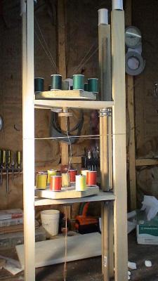
30 inch supports: the four long pillars at each corner (supports in picture are 36 inch)
Drive shaft: the long dowel (when you build this make sure to add a crank or handle on to it at the top.)
Pulley: the belt runs on this. (In the picture it is located below the two boards in the center on the ¾ inch dowel).
Tracer threads: the four white spools of thread (on your machine, the placement will be different as explained later).
• The Dies- The dies are simply a solid cylinder containing 8 groves across, and a funnel like cone with a hole in the center running throughout the length of the die.
- The dies process is as follows- there are two circular spinning surfaces, each surface has 8 spools of thread equally spaced from the die (which is in the center of the circle). The thread runs through the grooves in the die and out the bottom of the circle. When making the die it is good to use about 1/8th inch drill bit or one just a little larger. This will determine the thickness of the fuse. Make sure the second die has a hole two drill bit size larger than the first die in order to allow room for the second set of counter winding threads.
To construct the dies
Step one: Start with a 1 ¼ inch diameter dowel, cut a 3 inch long piece off.
Step two: Mark with a pencil the EXACT center of the dowel. Making the mark in the center of the dowel is crucial to making efficient and consistent weaves.
Step three: Using a drill press, carefully drill a 1/8th inch hole through the length of dowel starting at the center that you marked earlier.
Step four: Using a ½ inch cone shaped router bit drill an inverse cone (pointing inward) in the center of the dowel. When this step is completed you should have a dowel with a funnel in it.
Step five: Carefully make eight equally spaced marks around the dowel and using a hack saw cut ¼ inch deep slots at each of the eight marks made
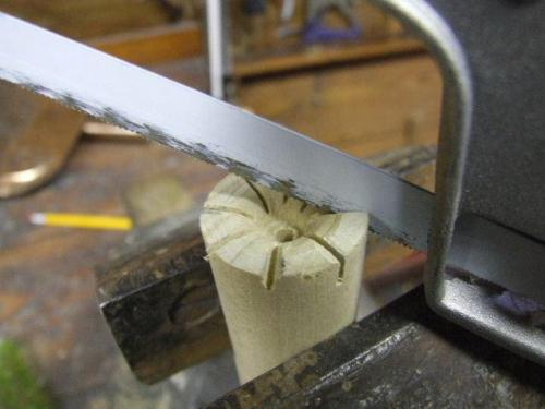
Using a vice to hold the dowel in place while making the 8 cuts
Congratulations you now have your first die, repeat this step a second time but use the next size up drill bit from the first one used. Remember to label this second die, die #2.
The turn tables
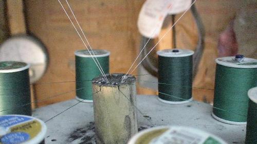
The turn tables house the dies (mention above), the 8 spools of thread and are what make the machine work. As shown above
THE PROCESS- the turn table spins, while it spins, powder is pulled through the funnel housing the powder by four threads called the tracer threads, this then gets fed through the hole made down the center of the die, and wrapped by the 8 threads. Basically the thread wraps itself around the powder as hard as that is to believe, that is what happens. Next, a second turn table which spins in the opposite direction counter-wraps the thread (in the opposite direction) to increase the strength of the weave.
HOW TO CONSTRUCT
Step one trace using a compass, a 7 inch diameter circle on a piece of ½ inch plywood.
Step Two: Using a jigsaw, band saw, or any type of saw, cut out the circle,
Step Three: Carefully, mark 8 equally spaced points 1 inch from the outside of the edge of the circle
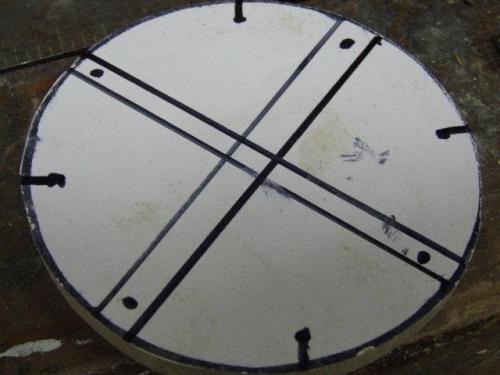
8 marks equally spaced around the circle
Step Four: Using an awl, hammer one indentation at each of the 8 marks made earlier. Then using a drill; drill eight ¼ inch diameter holes at each of the 8 points.
Step five: Cut a ¼ inch diameter dowel into 16 four inch long pieces. Next, place glue in each of the 8 holes made in the turn table and insert one piece of dowel into each of the holes after glue has been put in. this is what you will put your spools of thread on.
NOTE: make sure that your dowel fits through the hole in your spools of thread and can spin freely. If they don't, do the next smaller size dowel and drill bit for the turn table.
Step six: Drill a 1 ¼ inch hole in the exact center of the turn table.
Step seven: Add glue around the inside of the hole you just drilled, then insert the bottom of the die into the hole that you just drilled so that the bottom of the die is sticking 1 ½ inches out of the bottom surface of the turn table (the side with the 8 pegs is the top of the turn table).
Step eight: for the next few steps you will need a lazy Suzan type ball bearing.
Take your lazy Suzan and center it carefully over the bottom of your turn table, make sure the hole in the center of the lazy Suzan is centered over the center of the turn table.
Mark each of the four holes of the lazy Suzan's mounting system so you know where to put the screws. After they have been marked remove the lazy Suzan from the turn table surface and set aside.
You will need two turn tables as mentioned before, so repeat these previous steps to acquire both.
THE FRAME
The frame is very important it is what holds the visco machine together at the same time; the frame is also the simplest part of the machine. Construct the frame as follows.
Step one: cut four pieces of wood, the dimensions of these four pieces are ½ inch thick, 6 inches wide and 16 inches long. One of these pieces will be the base, two will each hold one of the two turn tables containing the dies, and the last will hold the funnel and tracer threads.
Step two: Cut four more pieces of wood this time with the dimensions, 2x1 with a length of 30 inches.
Step three: Taking two of the first four pieces cut (16 long x ½ inch thick x 6 inch wide). Line them up perfectly and clamp them together relatively tightly.
Step four: Mark the center of one of the two boards that are clamped together. The center should be 8 inches in from the end of the board and 3 inches in from the side of the board. At the intersection of these two points is the center drill a hole with a slightly larger diameter than 1 ¼ inch as to allow the bottom section of the die to spin freely in it. The two boards should both have a hole drilled in the exact same place. Make sure to keep the two boards together. DO NOT UNCLAMP THEM. Two inches in from the end of the board (does not matter which end) and 3 inches in from the same side as the first mark, drill a 7/8th inch hole through the two boards. This second set of holes is where drive shaft will go.
Putting it all together
Step one: Unclamp the two pieces of wood. Like earlier in the guide, you will have to mark where you are going to place the lazy Suzan, so center the lazy Suzan over the center of the board, and mark with a pencil, where the four holes will go.
Step two: instead of mounting the lazy Suzan directly two the board, we will instead insert four screws (one at each of the marks) through the bottom of the wood which are just long enough to stick out about 1/8th of an inch out the other side, the point of these screws are that the lazy Suzan which is fastened to the turn table will rest on these four screws. After you make sure that
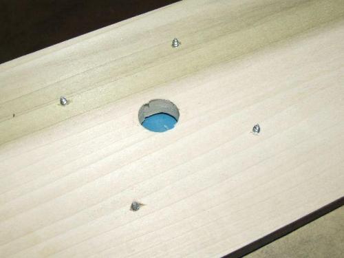
The lazy Suzan will mount onto these for points sticking out
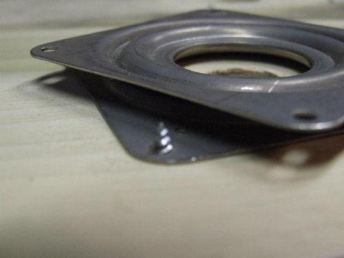
This image shows the mounted lazy Suzan
REPEAT this step on the other 16x1/2x6 board for the second turn table
Step two: At the four marks on the turn table's underside, mount the lazy Suzan. Do this step to both turn tables.
Step three: Take the four 30 inch long pieces, and start at one end of one of them and mark 12 inches up, continue from that mark and go another 12 inches up and make a second mark, then continue from this second mark. Repeat this step on all for 30 inch lengths of wood. At the first mark on each piece of wood, label it "one".
Step four: Take one of the turn tables and insert the bottom side of the turn table's Die sticking out, into the center of one of the two boards with the holes in it. Make sure the four screws sticking out of the board line up with the lazy Suzan's mounting holes; proceed to check if it spins properly. Repeat this step with the second turn table and second board.
Step Five: At the marks made in step three on the 30 inch pieces of wood, using screws, mount the two boards with the holes in them, it should start to look like the picture at the top of this page.
Step Six: On the bottom of the 30 inch pieces of wood, add one of the boards without holes, secure with one screw from each of the four 30 inch support beams into the bottom base board.
Step Seven: In the center of the fourth board, drill a hole with a size which your funnel's tip slides into and another 7/8ths inch hole in the same position as the other 7/8ths in holes in the other boards. Continue, by mounting this board on the top of the four supports. Around where the funnel goes, drill four ¼ inch holes and insert four more ¼ inch dowels, these will house the tracer threads.
Step eight: Acquire a 36 inch long ¾ inch diameter dowel, and also acquire two 2 inch pulleys (the kind that belts turn on power tools) make sure that the pulleys have a ¾ inch hole in the center.
Step nine: Starting at the top of the four boards Slide the ¾ inch dowel through the first two 7/8th inch holes, then slide on one of the pulleys, then slide through the next board, and ad the second pulley. Make sure you slide the pulleys up near the undersides of the boards above them, and then proceed to tighten them with an Alan wrench.
Step ten: Place the completed turn table # 1 on the second shelf from the top, make sure that it is secured by the four screws sticking out from the board it will be resting on. Then place the completed turn table #2 on the shelf below the first completed turn table.
Step 11: cut out a ½ inch thick by 2" wide by 5 inch long piece of wood, drill a ¾ inch hole at both ends, this will be the handle to crank it with, to complete the crank purchase another ¾ inch dowel, cut a 4" length of ¾ inch dowel and glue it to one end of the block of wood recently cut.
Step 12 (optional): if you would like to make your machine wind its own fuse onto a role, I would suggest building an automatic winding mechanism. This can be done by directing the rotation of the drive shaft into a gear which turns another gear which winds up your fuse onto a spool as shown below.
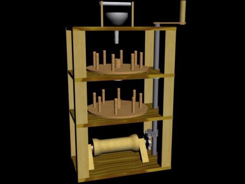
a much clearer picture of the machine (this machine is missing the tracer threads on top)
Set-up and Making it Run
Set up is quite simple acquire two large rubber bands, these will be your belts. Attach the first rubber band around the pulley under turn table number one and attach it so it is looped around the bottom half of the die sticking out the bottom of the turn table. Take the second rubber band and twist it so it makes an X, this is important, because this twist cause the second turn table to spin in the other direction so loop this twisted rubber band around the second pulley and connect it to the exposed portion of the die under turn table number two. Just purchase 20 spools of 100% cotton thread. Take 8 of the spools and place them on the 8 pegs of turn table #1. Then, take a thin piece of wire and stick it up though the die, and connect each of the 8 threads to this wire, also, place the 4 tracer thread spools on the top four pegs run these through the funnel and then tie them to the same wire that the other 8 threads are attached to. Then pull the wire down through the first die. Continue by tying the next set of 8 spools of thread onto turn table #2, at this moment there should be a total of 20 threads tied to the thin wire. Pull this wire through the second die, so it comes out the bottom. If you have decided to build an auto winding mechanism to automatically wind your fuse, then proceed by attaching the medley of twenty threads to the pin on the auto winder. All you need to do now is fill up the funnel with finely granulated black powder and start crankin' out the fuse.


